We can define the output from the op-amp using the equation

where Av represents the op-amp's voltage gain and the plus and minus signs on the voltages, V+ and V- , indicate that they are the input levels into the non-inverting and inverting input pins.
For the sake of illustration, let's use the SN741, which has a typical gain of Av = 200000 . If we apply 1.0 Volts to the inverting input and 1.00001 Volts to the non-inverting input the 741 will produce an output of

If we change the input levels to, say, 5.2 volts applied to the non-inverting input and 5.20001 volts applied to the inverting input, the output becomes...

i.e. exactly the same! This is because what matters is the difference between the two input voltages not their individual values. Note also that, since the voltage gain value is very big, we get a noticeable output of a few volts when the inputs differ by a just a few microvolts. For most purposes we'd regard 5·2 Volts & 5·20001 Volts as being 'identical', but they differ by enough to make the op-amp give a reasonable output.
This equation lies at the heart of the behaviour of a feedback amplifier system. The non-inverting input sees the incoming signal we want to amplify. The inverting input sees an 'attenuated' copy of the output being produced. The amplifer then responds if it sees any difference between these, changing the output to bring them into line. In effect, the op-amp uses the feedback to compare its output with its input and any 'error' makes it correct its output. The gain of the overall system is then defined by the choice of the feedback resistors which determine how small the 'fed back' copy of the output will be.
To understand how feedback controls the behaviour of the op-amp circuit we can being by remembering that the op-amp does have a very large current gain, so we can assume that any current which flows into its inputs is so small that we can regard it as being zero for most practical purposes. The pair of resistors therefore simply act as a potential divider. When the output voltage is Vout this means they put a level
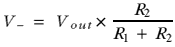
onto the non-inverting input.
To understand what this means, imagine that the circuit starts with all the input and output voltages at zero, that the op-amp's gain, Av = 100000, and that the resistor values have been chosen so that
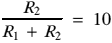
Since both input voltages are zero, the difference between them is zero, so even though we multiply this by 100000 we still find that the amplifier initially is happy to maintain an output of zero. But now imagine what happens when we apply, say, +100 mV to the input pin, V+ . When we do this, the amplifier suddenly finds that it should be producing an output voltage of

Now, the amplifier can't produce this instantly so the best it can do is wind up the output voltage it is producing as quickly as it can. Because of the feedback resistors, this means that the voltage 'fed back' and applied to the V- pin also rises - it is always a tenth of the the output level. Eventually, the output voltage reaches about 1 Volt... and stops rising any more!
The reason it stops is that the difference between the two inputs is now so small that 10000 times this difference is 1 Volt. As a result, the amplifier is happy to keep the circuit in this new 'steady state'. Since the output is ten times V- the feedback potential divider is also happy that the relationship between these two points is correct. Hence the system is happy to maintain this situation for as long as we keep applying 100 mV to the non-inverting input.
If we slowly vary the input we now find that the output 'tracks' any changes, always maintaining an output voltage which is ten times the input. Hence is we provide a varying input pattern to the circuit's input we get an amplified copy of the same pattern at the circuit's output. The actual output is whatever level satisfies two requirements:
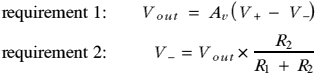
Which, for the values chosen for this example, means the output is about ten times the input.


 Content and pages maintained by: Jim Lesurf (jcgl@st-and.ac.uk)
using HTMLEdit2 on a StrongARM powered RISCOS machine.
University of St. Andrews, St Andrews, Fife KY16 9SS, Scotland.