6.4 Back to the power supply.
Having looked at the transformer, diode, & smoothing capacitor in isolation we can now put them together & see how the power supply circuit of figure 6.1 works.
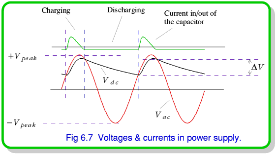
The input transformer ‘steps down’ the mains input to provide a 50Hz sinewave voltage,  , which swings up & down over the range
  to
to  as shown in figure 6.7. The value of
  depends on the turns ratio of the transformer. The voltage on the capacitor,
  , at any moment depends on how much charge it holds.
When  the diode is forward biassed. Current then flows through the diode, charging the capacitor. As
  rises to
  during each cycle it pumps a pulse of charge into the capacitor & lifts
  . Using a silicon diode we can therefore expect the peak value of
  to be
to be  Volts since the diode always ‘drops’ half a volt when it’s conducting. When
  swings below
  the diode stops conducting & blocks any attempt by charge in the capacitor to get out again via the diode. Since the mains frequency is 50Hz these recharging pulses come 50 times a second.
In the gaps between recharging pulses the dc current drawn out of the supply will cause  to fall. How much it falls during these periods depends upon the amount of current drawn & the size of the capacitor. The time between pulses will be
During this time a current,  , would remove a charge
from the capacitor, reducing the d.c. voltage by an amount
before it can be lifted again by the next recharging pulse.
As a result of this repetitive charging/discharging process during each mains cycle the output voltage ripples up & down by an amount  . Hence the output isn't a perfectly smooth d.c. voltage. However, from equation 16 we can see that it's possible to reduce the amount of ripple by choosing a larger value capacitor for the reservoir, C. Having chosen a suitable capacitor the circuit provides an almost steady d.c. output voltage when driven with mains a.c. Hence it works as a power supply.
Summary
You should now know that a capacitor can be used as a charge reservoir to smooth out swift voltage variations and that it's possible to use a resistor-capacitor circuit as a low-pass filter. That the behaviour of this kind of filter is a sort of ‘inverse’ of the high-pass filter in the previous lecture.
You should also know that we can make a diode by joining together two pieces of semiconductor — one N-type, the other P-Type. That the forces between charges near the PN-Junction produces an effect which means that the diode only conducts a significant amount of current when forward biassed. That, for many purposes we can assume the diode's IV relationship is a square-law, or even simplify it to assuming that current only flows when the diode's forward voltage is 0·5 Volts.
You should also understand that a transformer is a two or more coils of wire linked by a common magnetic field. That this allows us to ‘step up’ or ‘step down’ the size of an a.c. voltage by an amount which depends upon the transformer's turns ratio. Finally, you should now understand how the combination of a transformer, diode, & capacitor can act as a mains power supply to convert 50 Hz mains sinewave power into a fairly steady d.c. voltage. That this voltage will, however, ripple by an amount which depends upon the size of the reservoir capacitor and the current drawn from the supply.








 Content and pages maintained by: Jim Lesurf (jcgl@st-and.ac.uk)