
The main property of a capacitor is that the voltage ‘on’ it (i.e. the potential difference between its leads) is proportional to the charge it has stored. This makes its behaviour very different to a resistor where the voltage across the resistor is proportional to the current flowing through it. To understand the consequences of this consider the situation illustrated in 4.4a. Here a signal generator is applying a voltage


to a capacitor.
In order to force the capacitor voltage to vary with time we have to keep shifting charge from plate to plate. The faster we want the voltage to change, the more quickly we have to move charge — i.e. we can expect the current flowing through the capacitor to vary in proportion to the rate of change of the voltage. (Actually, different electrons move onto one plate & off the other so ‘through’ is strictly incorrect, but since all electrons look the same that doesn't matter!)
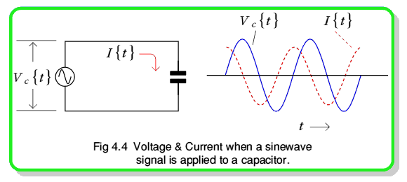
When we apply a voltage sinewave we get the results indicated in figure 4.4. This shows that the current variation is also a sinewave, oscillating at the same frequency as the applied voltage. However, the current is ‘out of step’ or out of phase with the voltage variations. To see why, consider what happens as the voltage changes. Equation 14 tells us the voltage on the capacitor at some moment, t. At that time it holds a charge


A short time,  , later it will hold a charge


This means that, during the time interval from t to  , the capacitor charge must have changed by an amount


By looking through a maths book we can discover that


so we can re-write equation 17 as


We're interested in how the current & voltage vary from moment to moment so we can deliberately chose a value for  that's much less than the time required for one sinewave cycle — i.e we can arrange that
  . Since the sine of a small angle has almost the same value as the angle (in radians) this means we can say that
  . We can also say that the small value of
  means that
 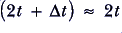 . Hence we can simplify equation 19 into


(Strictly speaking, expression 20 should say these quantities are only approximately equal to each other. However, provided the time interval is small enough, they're so similar that we can ignore this and treat the result as an equality.)
Electrical current is defined as the rate at which charge flows. We can therefore define the current around the circuit at any instant to be


Looking in the maths books again we can discover that  , so we can rewrite the current as


This agrees with the graphs shown in figure 4.4. The current flowing around the circuit & through the capacitor varies sinusoidally at the same frequency, f, as the applied voltage. However, the current variations lead the voltage variations by a phase angle of  or 90°.
When dealing with resistors we define the resistance value as the ratio  . If we tried doing this with a capacitor we'd get a ‘resistance’ of


This isn't much use. What we'd really like is a single number like a resistance that tells us the relative sizes of the signal current & voltage in the circuit. Instead, equation 23 varies with time from  to
to  ! To get around this problem engineers have invented a quantity called the reactance of an electronic component (or circuit). This can be defined as the ratio of current to voltage, but considered ‘90° out of phase’ with one another. Since a single sinewave cycle take a time
  to complete a 360° phase change a 90° takes a time =
  . We can therefore define the value of the reactance, X, by the expression

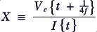
using this we can say that, for a capacitor


This provides us with a value which doesn't zoom up and down all the time. It indicates the relative magnitudes of the applied voltage and current oscillations. We can use it to say that an applied sinewave voltage,


will set up a current

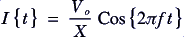
through the capacitor.
Note that — unlike a resistance whose value doesn't depend upon the details of the applied signal — the value of the capacitor's reactance does depend upon the frequency of an applied sinewave. For this reason the reactance only means something when we're using sinewave signals.
Summary
You should know that there are various ways to specify the size of a signal voltage (or current) which varies with time. For simple, repetitive waveforms like sinewaves we can use a 'scope and measure a peak to peak size. For more complex signals we can use the root mean square size. You should remember that an rms measurement is one taken by averaging the squared quantity over some period of time and taking the root of the result. That this gives us a value which essentially represents the size of a steady (d.c.) voltage which would provide the same signal power. That, for a sinewave, we can calculate the rms voltage from the observed peak to peak voltage using equation 10.
You should also know that the voltage on a capacitor is proportional to the charge it holds. That the charge accumulated (& hence the voltage) = current  time when we apply a steady current. That there are various types of capacitor, some layered or rolled up to get more capacitance into a convenient size & shape. That electrolytic capacitors are polarised by an electrochemical process. This means that they can pack lots of capacitance into a small volume, but won't work properly if we apply a steady voltage to them in the ‘wrong’ direction. Also, that any capacitor will fail if we apply a voltage above the breakdown voltage which destroys the insulating layer between its plates.
Finally, you should now know that when we apply a sinewave voltage to a capacitor the resulting current also varies sinusoidally at the same frequency but is 90° out of phase with the voltage. This means we can't use a resistance value to indicate the ratio of the current & voltage values. Instead, we use the reactance which, unlike resistance, has a value which is frequency-dependent.


 Content and pages maintained by: Jim Lesurf (jcgl@st-and.ac.uk)
using
TechWriter Pro and HTMLEdit on a StrongARM powered RISCOS machine.
University of St. Andrews, St Andrews, Fife KY16 9SS, Scotland.