The mathematical arguments explained in detail above can be simplified into the rules described in the ‘resistor rules’ appendix. In general it's easier to remember and use the simple rules given there when you want to work out the behaviour of an arrangement of resistors. This section of the lecture uses the loaded potentiometer to illustrate the concepts of equivalent circuits and output resistance. These concepts are very important in general electronics. However, in most practical situations the rules in the appendix are all you need to work out the main effects of a resistive circuit.
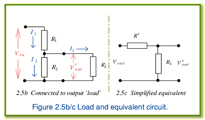
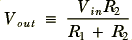
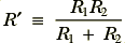
The behaviour of the circuit shown in figure 2.5b can be represented in terms of a simplified equivalent circuit shown in figure 2.5c where we define
and
In effect, we're treating the unloaded output,  , as a sort of ‘internal voltage’ (or electromotive force) produced by the combination of the actual input and the volume control.
  is an effective output resistance of the volume control which sits between the internal voltage and the output load.
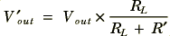
Note that this equivalent circuit is an example of applying a general rule called Thevenin's Law which states that any circuit made up of lots of resistors and voltage sources can be simplified into an internal voltage in series with an output resistance. To show that 2.5c is equivalent to 2.5b we can analyse its behaviour. This is fairly easy once we notice that 2.5c and 2.5a have exactly the same form. Since all the current flowing through  must also flow through
  we can say that
and
Combining & rearranging these we obtain
To check that this is correct we can use expressions 17 & 18 to replace  and
and  and we then find that
i.e cancelling factors of  we get
which is the same as expression 15. Hence we can regard the combination of the volume control (potential divider) and its input signal as being equivalent to the voltage given by expression 17 seen through a series resistance whose value is given by expression 18.
In this case reducing circuit 2.5b to 2.5c hardly seems worth the effort. However, it is worth remembering that this is just a simple example of a general rule which can be used to reduce very complicated arrangements of resistors & signal sources to just one voltage source and one resistor. It also makes the point that the volume control will have an output resistance equal to  , the parallel combination of the resistances of the two sections of track from its wiper to its two ends.
Note that all real signal sources will have a non-zero output (series) resistance. Some signal source have very low output resistances, but it can never actually be zero — otherwise it might be possible to draw infinitely big currents and powers from the source. This is physically impossible. All real signals have finite non-zero energies and powers.
Summary.
You should know that resistors and conductors obey Ohm's Law which tells us that the current produced by an applied voltage is proportional to the voltage,  , and depends upon the Resistance, R, of the piece of material. That the amount of electrical power we have to provide to drive a current through a resistor is
  and that this power is dissipated, warming up the resistor.
You should now also know that resistors come in two general types — fixed, and variable ‘pots’. That the values generally available follow a specific series of values and that the values of fixed resistors are usually printed on them as a series of bands or rings according to a standard colour code.
You should now understand that a volume control is an example of a variable potential divider which can be used to adjust the signal voltage level. That anything we connect to the output must draw some power and ‘load’ the circuit by an amount which depends upon its input resistance. You should now also know that a circuit like the volume control can be described in terms of a simplified equivalent circuit and that it, like all real systems, will have a non-zero output resistance.


Content and pages maintained by: Jim Lesurf (jcgl@st-and.ac.uk)
using HTMLEdit and TechWriter on a StrongARM powered RISCOS machine.
University of St. Andrews, St Andrews, Fife KY16 9SS, Scotland.