
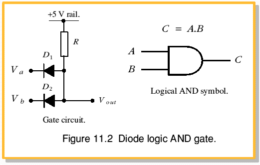
Figure 11.2 illustrates a diode logic circuit which can provide the AND function. It also shows the standard symbol for a logical AND gate. In this case the output is connected to a +5V power line through the resistor, R. So unless we do something to drag down the output voltage it will sit at about 5V. (i.e. C will be “1”). However, if we make either Va or Vb equal 0V one of the diodes will conduct and pull Vout down to about 0·5V. In this case therefore the truth table is as follows.
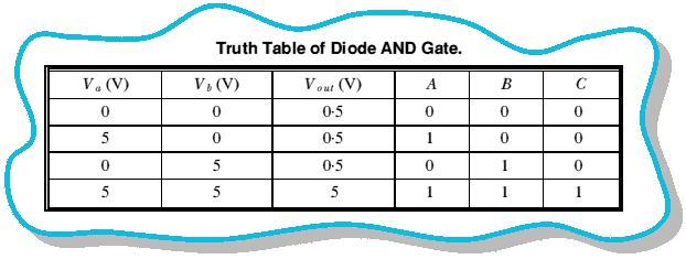
In this case the output will only be “1” (i.e. above 2·5V) when both inputs are high. So the circuit performs the logical function,

and ‘C equals “1” only when A and B both equal “1” ’.


 Content and pages maintained by: Jim Lesurf (jcgl@st-and.ac.uk)
using HTMLEdit2 on a StrongARM powered RISCOS machine.
University of St. Andrews, St Andrews, Fife KY16 9SS, Scotland.