

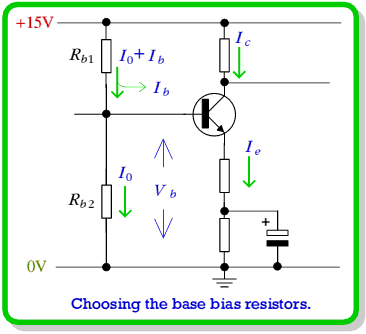
 , to be around 5·6 volts. The two base resistors act as a sort of potential divider and we can choose their values to set the voltage we require. To do this we need to use Ohms Law and recognise that the current through
  provides the base current and the current which goes on through
  .
.
 since the currents in these resistors will be almost exactly the same and we want to have 5 volts across each of them (Ohm's Law).
 value at a particular point on its curves (
 mA,
mA,  V). So let's choose to try and set the amplifier up with a collector current of about 2mA. We therefore want the currents passing through
  and
and  to be 2mA. You now know the current in each of these resistors and the voltage across each of them. Using Ohm's Law, what values do you calculate are required for
  and
and  ? What is the closest ‘E12’ series value available in the lab? Use this value for the emitter and collector resistor in your circuit.
 will continue on through
  and part will enter the transistor to provide its base current.
  . Using Ohm's Law again we can say that
 to be 5 volts, we want
  volts, so we can say that


 ,
,  , and
, and  . To proceed any further we have to choose a sensible value for one of these.
 , which passes through both resistors. In theory, we can choose any value we like. However, in practice it turns out to be a good idea to choose a value
  since this means that the voltages across the resistors are largely determined by
  . This means that any slight changes in
  won't mean we've got the wrong results. However, we don't want
  to be too big. The reason for this is that we would get a large current by using very low resistance values. These would make it difficult to apply an input ac voltage when using the amplifier.
 so I suggest you choose that. Note, however, that you could choose almost anything from
  up to
up to  and it would still probably be possible to make the amplifier work despite having chosen very different currents and resistor values!
 (‘rule 2’). You can follow the argument I describe below, but substitute the
  you measured to get the correct results for your transistor.
 mA the current entering the transistor's base is
 A. Multiplying this by 25 we get
  125
125 A. Putting this into the above equations we get
  k
k and
and  k
k . What values do you get for your transistor? What are the closest E12 series values available to use in your circuit?
 ,
,  ,
,  , and
, and  . However, we now need to decide what to do with
  ...
...
 is actually quite important as it turns out to control the voltage gain of the amplifier. To understand why this is true, have another look at figure 6 and consider what happens when we quickly waggle the input voltage up an down with an ac signal. In order to change the voltage across
  we also have to change the voltage across
  as they are connected in parallel. To change the voltage across
  we have to move charge in or out of the capacitor. This takes time. So if we keep changing our mind and waggling the input voltage up and down quickly we don’t give this a chance to happen.
 effectively ‘clamps’ the voltage at the top of
  and won’t allow it to change. The transistor’s base-emitter voltage remains about 0·6V. Hence the changes in input voltage mostly appear as changes in the voltage across
  .
.
 , therefore tends to produce an ac current variation in
  of
of


 is relatively tiny (hundreds of times smaller than
  or
or  ) we now expect the same current fluctuation to appear in
  . So the voltage across the collector resistor will vary by an amount


 which reasonably small compared to
  , we can leave the other resistor values alone and not worry that we have changed the DC levels very much. A small value will also mean a high gain.

| What value of  will give your amplifier a voltage gain of around × 20? will give your amplifier a voltage gain of around × 20?
|
|
| Choose the nearest E12 resistor value for your circuit. What value is this, and what value of gain do you it expect it to provide? |


 Content and pages maintained by: Jim Lesurf (jcgl@st-and.ac.uk)