
We can easily make antennas which are more directional than a simple dipole. This ‘squeezes’ the radiated power into a smaller range of angles, hence increasing the gain and power density along the directions where the function which describes how the radiated power varies with the two direction angles,

is highest. The details of a real antenna's power pattern can be quite complex and will depend on how we've made the antenna. Figure 6.4 shows how we can represent a typical antenna pattern. Here the real pattern is a ‘solid shape’ which illustrates the relative power densities radiated in each direction. The total power radiated in all directions will be proportional to the volume of this shape.
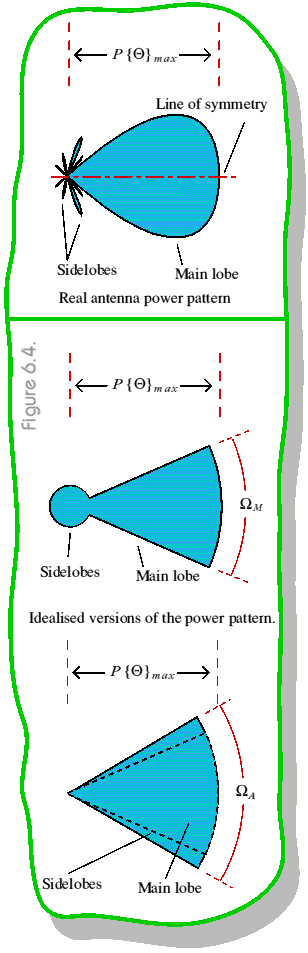
We can locate the direction of highest power density and call it the axis of the antenna. (It is also sometimes called the antenna's boresight). For the sake of simplicity we'll assume that the patterns we're considering have rotational symmetry about this axis. Hence we can ignore one angle and specify the power pattern simply in terms of the angle ‘off axis’. The power density radiated along the axis will be, from the above definition of the axis, be the peak level

The real pattern of most practical antennas can be divided into one Main Lobe which includes the axis, and a set of Sidelobes pointing in other directions. The on-axis Gain of the antenna can now be defined to be
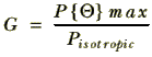
where Pisotropic is the power density which would be radiated uniformly in all directions by an isotropic radiator fed with the same total power.
The total power radiated into a given solid angle is proportional to the part of the shape's volume which fits inside that angle. We can simplify the main lobe shape by readjusting its volume into an ‘idealised’ main lobe which has a uniform power density equal to the peak level over some solid angle,

This angle of the ‘smoothed out’ main lobe is called the antenna's Main Lobe Angle. In the middle illustration of figure 6.4 the remaining sidelobe power is smoothed out to a uniform power density in all directions except the idealised main lobe.
This simplified picture actually turns out to be good enough to let us describe most of the main properties of a real antenna, despite having discarded almost all the details of the real pattern. We can, in fact, take this process one stage further and redistribute the sidelobe volume/power ‘around the sides’ of the main lobe. This produces the pattern shown at the bottom of figure 6.4. Here the antenna power pattern is assumed to have a uniform power density equal to the peak level over a solid angle,

and that none of the power is radiated outside this solid angle. The angle is called the Antenna Angle of the antenna. If we compare this idealised pattern to a sphere containing the same volume (i.e. the power pattern of an isotropic radiator emitting the same total power) we can show that
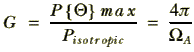
i.e. the more directional the antenna is (the smaller the angle), the larger its gain will be.


 Content and pages maintained by: Jim Lesurf (jcgl@st-and.ac.uk)
using HTMLEdit3 on a StrongARM powered RISCOS machine.
University of St. Andrews, St Andrews, Fife KY16 9SS, Scotland.