15.2 Improved forms of radar.
Before going on to consider alternatives to radar it is worth mentioning some of the improved forms of radar which have come into use. These don't overcome the basic problems mentioned in the previous section, but they have some advantages over traditional pulsed radar. Here we'll consider Continuous Wave Frequency Modulated (CWFM) and Doppler radar techniques. Millimetre-wave systems using these methods are currently being developed for automobile ‘cruise control’ and ‘collision avoidance’ applications. The use of these methods provides very high precision at low ranges. In a CWFM system the transmitted power is held constant (hence producing a ‘continuous wave’ rather than a chain of pulses). The sensitivity of a radar depends upon how much reflected energy it can gather in a given time. In pulsed systems the peak power must therefore be high since, most of the time, no power at all is being transmitted or received. CW radars can therefore often use steady power levels two or three orders of magnitude lower than the peak levels required for comparable performance from a pulsed system.
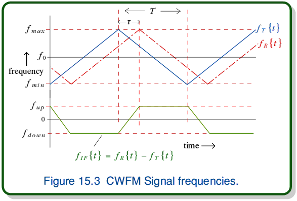
The pulses of a conventional radar provide convenient transmitted signal markers which are used to determine the time taken for a wave to travel to the target and back. When using a CW transmission we have to modulate the signal in some other way. The simplest way to do this is to sweep the wave's frequency up and down regularly in a triangle-wave. This process is illustrated in figure 15.3.
 represents the pattern of frequency variations transmitted by a CWFM radar.
  represents the pattern of a reflected signal which returns to the radar after a time delay, t. During a ‘sweep up’ the signal frequency is steadily increased from
  to
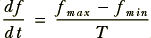
to  over the period, T. i.e., the rate at which the transmitted frequency is ramped is
By using a heterodyne mixer we can combine the transmitted and returned (delayed) signal frequencies and obtain an output
During the ‘flat’ part of the up-sweep the time delay means that
During the ‘flat’ part of the down-sweep a similar argument means that
(Note, the ‘negative frequency’ for  arises because during this part of the sweep cycle
 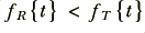 . Since
  a simple heterodyne system produces an output which ignores which of the two input frequencies is larger. Hence we would just see a cosine wave of frequency
  . Despite this, although we won't bother with them here it is possible to build systems which can distinguish between a ‘negative’ frequency and a positive one.) By recording the
  pattern produced by the transmitted wave's FM we can, knowing T,
  , and
, and  , use
, use  and
and  to determine the delay,
  , and hence discover the target range. We can also determine t from the lengths of the ‘crossover’ regions of
  where the output frequency switches from
  to
to  and vice versa.
In reality, many targets tend to move with respect to the radar system. Slow movements can be tracked by observing how  varies with time. An alternative method is to use the Doppler effect. A target which is closing range (i.e. approaching the radar) with a velocity, v, will shift the returned frequency by an amount
Where  is the transmitted ‘center frequency’ and — for the sake of simplicity — we'll assume that
  . (The factor of 2 appears because the radar is essentially seeing a reflection of itself in the target ‘mirror’. This image appears twice as far away as the target, hence it approaches twice as quickly.) This movement alters both ‘flat’ frequencies to
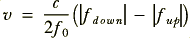
Note that since the signs of these frequencies differ the doppler shift has the effect of increasing the magnitude of one and reducing that of the other. Hence we can calculate the target's velocity along the line of sight from















 Content and pages maintained by: Jim Lesurf (jcgl@st-and.ac.uk)