
In practice we often want to do more than just carry power from place to place. The purpose of most instruments is to process the information carried by an EM wave or beam. This means we have to devise and use optical devices in addition to simple lenses, mirrors, and feeds. To illustrate this process we can use the devices used for polarisation state processing. This method of signal processing can provide very high levels of performance. The basic optical passive elements required are polarisers and roof mirrors. For signal frequencies up to the mid-infrared, the best form of polariser is based on a free standing wire grid. The actions of each rely upon the properties of a metallic reflecting surface.
An EM field incident on a plane metal surface will set up a current along the surface. This current produces an EM field whose E-vector, in the plane of the surface, is almost perfectly equal and opposite to that of the incident field. In effect, the current produces a ‘reflected’ wave whose E-field along the surface cancels that of the incident field. This is the basic mechanism behind metallic reflection, usually described as “The net electric field along a metal surface is always zero”.
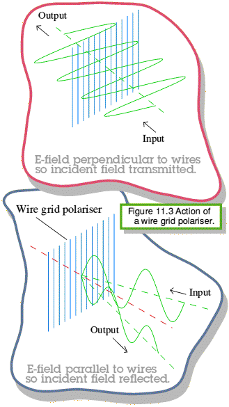 The behaviour of a wire grid polariser is illustrated in figure 11.3. The polariser consists of a parallel array of metal wires, all arranged in the same plane. The diameters of the wires and the spacing between them are arranged to be small compared to the wavelength of the incident radiation. An incident electric field whose E-vector is parallel to the wires will set up currents along them just like it would in a metal surface. The wires therefore reflect a parallel E-vector field just like a mirror. An incident field whose E-vector is perpendicular to the wires can't set up a current. This is because the wire diameter is very small. Any movement of charge across the wires almost immediately causes a difference in potential across the wire which then opposes any further current flow. Hence an incident field whose E-vector is perpendicular the the wires can't set up an appreciable current. It therefore ‘doesn't know the wires exist’ since the wires & field don't interact and it passes straight through the plane array of wires without being affected.
A proper theoretical analysis of a wire grid polariser is more involved than the above explanation, but it leads to the same conclusion. It we shine an EM field onto the array the E-vector field component parallel to the wires is reflected just as if the polariser were a mirror. The E-vector field component perpendicular to the wires is transmitted through the polariser almost as if it didn't exist. Wire grid polarisers are useful devices because their behaviour is almost frequency independent over a very wide range. Once there are more than about 10-20 wires per wavelength their dissipation, scattering, and cross-polar losses are quite small — typically less than 0·1% of the incident power fails to go where we'd expect by assuming perfect behaviour. For frequencies up to a few THz we can make grids by winding 5 or 10micron diameters wires onto a frame. At higher frequencies similar polarisers can be made using photolithograph or chemical processes.
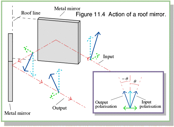
A roof mirror consists of two plane metal mirrors jointed together at 90 degrees. This makes a shape a bit like the roof of a house — hence the name. The action of the roof mirror on a polarised beam is illustrated in figure 11.4. This shows a single ‘ray’ of a beam which is directed onto the mirror. The input beam is plane polarised at an angle to the roof line which is the line linking the two plane mirror surfaces. The properties of a metallic reflector mean that the E-field vector is ‘flipped’ each time it is reflected. The roof mirror therefore has the property of reflecting a beam and rotating its plane of polarisation through an angle twice that between the input E-field and the roof line.
In most situations we arrange to illuminate the roof mirror with a beam which is plane polarised at 45 degrees to the roof line. The reflected beam therefore emerges plane polarised at 90 degrees to the input. These input and output polarisation states are said to be Orthogonal. If one of them was transmitted by a polariser, the other will be reflected. Hence we can use a roof mirror to alter the polarisation state of a beam and change the effect a subsequent polariser will have upon it.


 Content and pages maintained by: Jim Lesurf (jcgl@st-and.ac.uk)
using HTMLEdit3 on a StrongARM powered RISCOS machine.
University of St. Andrews, St Andrews, Fife KY16 9SS, Scotland.