
The main requirement for single mode operation of conventional microwave guide is that the width of the guide a is around a half-wavelength. This would require us to make impractically small guides for signal frequencies above about 100 GHz. At mm-wave, terahertz, and higher frequencies Free space beams are a more convenient way to carry fields from place to place. To understand the properties of these beams we can imagine a beam which is essentially moving parallel to the z direction but whose width is not very large compared with the radiation wavelength. Such a beam field is said to paraxial to the z direction or axis. For simplicity we can assume that the EM field satisfies a linked set of scalar wave equations of the form


where  and y is the field (which we can identify as one E-field component)


Most of the field's z—dependence is assumed to have been placed in the  term, hence we can assume that

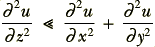
This lets us approximate the scalar wave equation and write

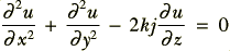
The solutions of this differential equation are known. From them we can define a series of Free Space Gaussian Beam Modes,


where




and  is the Hermite Polynomial of order m.
  is a complex number whose value is a measure of the field's overall amplitude and phase. r is the distance from the (
 ) beam axis.
Unlike the situation in metallic guide, these modes are TEM waves — i.e. both the electric and magnetic fields are perpendicular to the direction of propagation — and have no cut-off wavelength/frequency. The fundamental (lowest) mode is therefore the  mode
mode


which can, in principle, propagate power at any frequency.
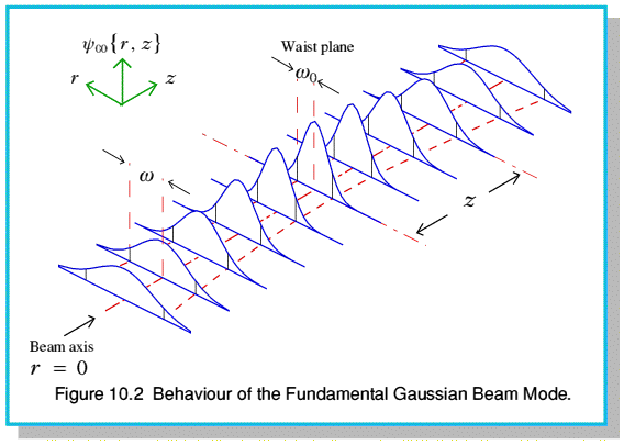
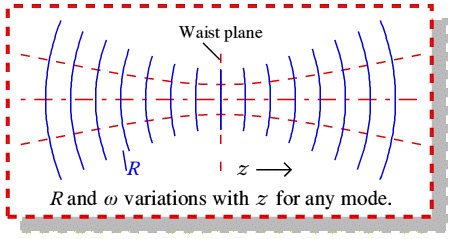
 is the beam's cross-sectional size or radius at any z-plane and R is it's Phasefront radius of curvature at any z-plane. From 10.20 we can see that the beam radius varies hyperbolically along the beam. It's minimum value,
  , is called the Beam waist radius. For simplicity, the origin of the x,y,z Cartesian co-ordinate system used above has its origin at the beam center in the beam waist plane. Hence z is the ‘down-beam’ distance measured from the waist plane. The basic properties of these modes are illustrated in figure 10.2. Two points are worth noting.
Firstly, the variations of and R with z are independent of the mode numbers, m & n. This simplifies the analysis of a multi-mode beam. It means that modes which share the same  and
and  will have the same sizes and phasefront radius everywhere along the beam. Secondly, the effective phase rate (propagation constant) of each mode is

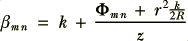
The presence of the Anomalous phase term,  , means that — as with waveguide modes — this phase rate is mode dependent. Note, however, that this term also means that the rate varies along the beam since it is a nonlinear function of z. Note also that the presence of the
  term means that the phase rate varies as we move off-axis. (This is why the beam ‘diffracts’ in the manner we observe.)
The most important consequence of these Gaussian Beam Modes is that we can specify any free space beam in terms of a linear superposition of these modes. Once this is done we have obtained an algebraic expression for the field everywhere along the beam. This means we can take diffraction and propagation effects into account without having to perform lots of numerical computations or awkward integrals. Another consequence of practical value is that we can expect a single mode beam to propagate maintaining its cross-beam field shape — although the distribution may change its overall ‘width’ along the beam as  changes. This permits us to use optical beams in the same way as waveguide modes. We can send signals from place to place in well defined beams. As a result we can assemble instruments and information processing systems using this technique in place of wires or waveguides.
As with single-mode waveguide modes, a single mode free space beam will propagate at a well defined phase rate and will maintain its cross-beam field pattern along the beam (although its width will be ‘stretched’ by  ) Also, like waveguide, a multi-mode beam will have a field pattern which varies along the beam as the various modes move ‘in and out of phase’ with each other due to their differing phase rates.


 Content and pages maintained by: Jim Lesurf (jcgl@st-and.ac.uk)
using
TechWriter Pro and HTMLEdit on a StrongARM powered RISCOS machine.
University of St. Andrews, St Andrews, Fife KY16 9SS, Scotland.