Photodetectors are generally considered as
being completely different to conventional diodes. Despite that, they turn
out to have some similar properties. Generally speaking, we can divide
photodetectors into two general types:
i) Photoconductors & other ‘bulk effect’ detectors;
ii) Photodiodes.
Here we'll concentrate on photoconductors, but we would in fact get a
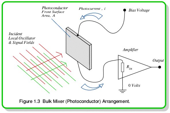
similar result if we examined the behaviour of photodiodes. Figure 1.3
illustrates a photoconductive detector being illuminated with some
electromagnetic radiation. The useful property of a photoconductive material
is that, when we apply a suitable bias voltage and illuminate it with
suitable radiation it conducts a current whose magnitude is proportional to
the light power falling upon it.
The current passing through the photoconductive detector can be said to be


where i is the current, P is the light power level, f is the light's frequency, h is Planck's constant, q is the charge on an electron.
 is called the Quantum Efficiency of the photodetector. This is the chance that a photon hitting the material will ‘liberate’ an electron from orbiting an atom inside the detector, allowing it to move freely and contribute to the current. The physical argument behind equation 1.10 is that a power, P, will consists of
  photons per second. These tend to produce
  freed electrons per second, each having a charge, q. Hence the current produced by the incoming power is as given by 1.10.
In the situation illustrated in figure 1.3 the photoconductor has an illuminated surface area, A, and we are shining two electromagnetic waves onto it. These are a signal electric field, 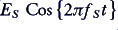 , and an LO produced field,
 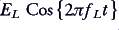 . The total field at the detector surface any any instant, t, will therefore be


In free space the ratio of the sizes of magnetic and electric fields is the Free Space Impedance,  . Using this, we can say that the power falling on the photoconductor at any instant will be


In most cases of practical interest we find that the signal and LO frequencies are similar — i.e.  . When this is true we can say that the detector current at any moment will approximately be


where

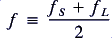
is the approximate value of the signal and LO frequencies. Looking at equation 1.13 we can see that the output current depends upon the square of the applied electric field. In this way the photodetector is similar to the diode we considered earlier — it is a square law device. Putting equation 1.12 into 1.13, using trig identities, and rearranging, we get



If the signal and LO frequencies are very high — e.g. visible light, or at least high microwave/millimetre-wave frequencies. then current fluctuations at the frequencies,  ,
,  , and
, and  are so high that they won't be able to be travel along the wires connecting the photoconductor to the amplifier. (And if they are, the amplifier will probably ignore them!) As a result the amplifier will see a current


where

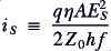
is the steady current level the photoconductive detector would produce if it were just illuminated by the signal,

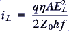
is the current produced by the LO alone, and

is the current fluctuation produced as the two waves move in and out of phase.
This oscillatory output current has similarities to the difference frequency output from a diode mixer. Its amplitude, frequency and phase are related to those of the signal in much the same way. As a result we can make a heterodyne system using a photoconductive detector as a mixer in place of a conventional diode. The importance of this result is that photodetectors can be made to operate at signal frequencies well above those possible with conventional diodes. Hence we can build and use heterodyne systems at visible frequencies and above. Using either form of mixer (or any other suitable nonlinear device) we can convert a high frequency input into a lower frequency output. This is convenient because we can often amplify and measure lower frequencies more easily. As a result, heterodyne systems are very useful when we want to make measurements upon high frequency signals or waves.


 Content and pages maintained by: Jim Lesurf (jcgl@st-and.ac.uk)
using
TechWriter Pro and HTMLEdit on a StrongARM powered RISCOS machine.
University of St. Andrews, St Andrews, Fife KY16 9SS, Scotland.