The Arduino series of boards provide an extremely low-cost analog-to-digital converter with DC-coupling that makes them ideal for simple chart-recorder purposes. The DataView-Arduino combination can thus be used in a wide variety of laboratory teaching applications.
The maximum Arduino sample rate that Dataview supports is 5 kHz, which is (just) acceptable for intracellular recording. (Of course, a suitable intracellular amplifiier is also required.)
The software Sketch needed to program the Arduino is provided, along with tutorial instructions for installation.
DataView supports DataTranslation data acquisition and stimulating modules. It has been tested with the DT9812 (Econ series) and the DT9818 USB boards.
NOTE: before purchasing a DT board it is strongly recommended that you borrow one (ask the DT sales person) and test it to make sure that DataView is able to carry out the acquisition and stimulating tasks that your project requires.
The exact facilities available obviously depend on the hardware on the DT board that you use, but the following describes the general options supported by DataView.
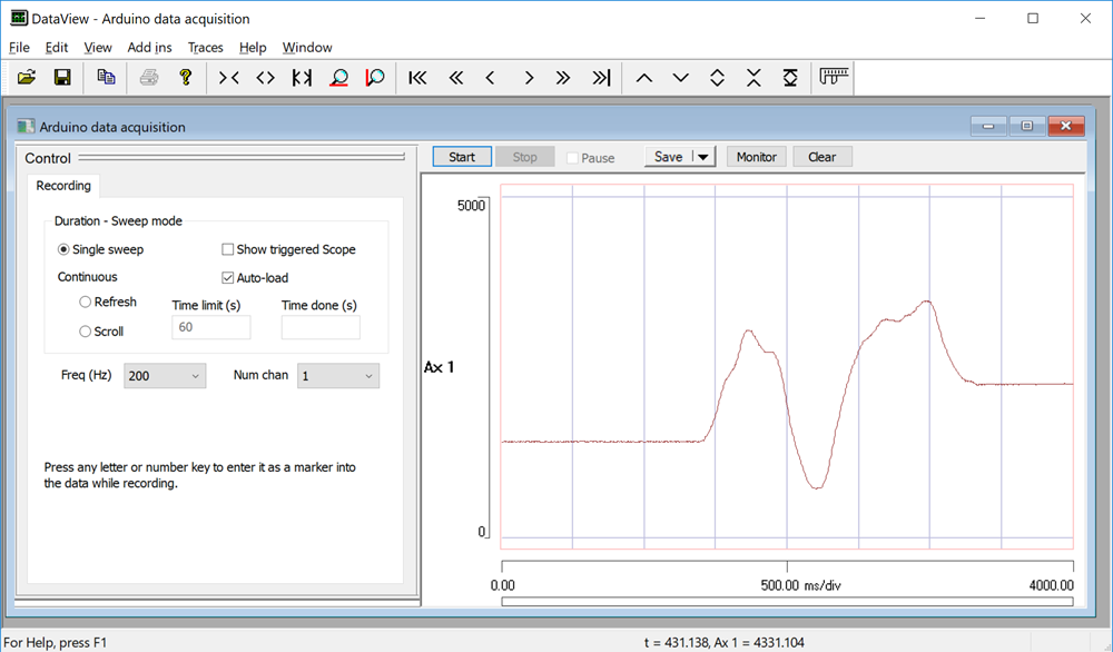
Data can be recorded on up to 16 channels, with all channels acquiring at the same user-specified sample rate. Acquisition can be triggered either manually by clicking the Start button, or in response to an external TTL electronic pulse, or at timed intervals.
In the recording above all control parameters were left at their default values: I simply started the system, put my finger on the input terminal of the first data channel to generate some mains interference (50 Hz, being the UK), and then clicked the Start button. The recorded data are displayed in the main view to the right, while recording and stimulating parameters are controlled through the dockable tabbed Control panel to the left. Start, Stop and Save options are controlled using buttons above the main view.
Each triggered acquisition constitutes an episode of data. Episodes can be of any specified duration, and you can stop acquisition mid-episode if you wish. You can set the acquire mode as single-sweep, or multi-sweep with refresh, or scrolling. You can manually or automatically append multiple episodes into a single data file, with the start of each episode marked by an event, or you can save multiple episodes into separate files, with automatic sequential numbering.
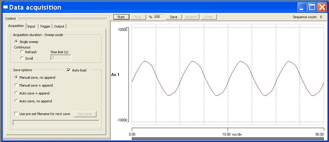
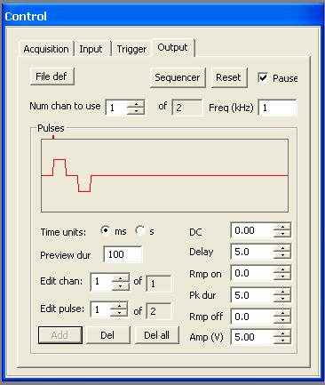
Two types of output are supported: waveform and pulse. To output a waveform you first have to load it into DataView for standard display. You then select it by clicking File def on the Output tab (below left). It will be output at the internal sample rate of the of the waveform itself, although this can be altered manually.
You can output an arbitrary collection of pulses superimposed on a specified DC level for each channel. Each pulse has a delay, ramp on, peak duration, ramp off, and amplitude. Pulses which overlap combine additively, so complex shapes can be defined.
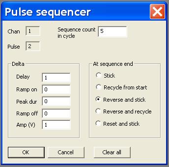
You can set up a Sequence (below right) for any pulse, so that its parameters each change by a specified amount after each episode. For the sequence shown, the delay and amplitude of pulse 2 will step increase by 1 unit for each acquisition/output of 5 episodes, and will then step decrease for the next 5 episodes back to the initial values, and then will stick at these values for any remaining episodes.
Software simultaneous start of AD and DA systems (which is all that is supported for the Econ series boards) does not provide completely accurate synchronization on DT boards. There may be jitter of a few clock cycles between the start of input and the start of output. This would not matter at all in some experimental circumstances, but would obviously be unsatisfactory for, e.g. extracellular stimulation and recording on a millisecond timescale, where you might want to overlay multiple episodes. The results would be accurate, but you would have to align them on the stimulus itself rather than simply on the start of the sweep.
Precise synchronization can be achieved by using an external trigger for both input and output. This can be achieved with an external source, or by using digital output from the board itself. DataView supports this by offering a start option where the AD and DA subsystems are armed for external triggering, and this is immediately followed by a 0-1-0 output sequence from the digital I/O port. If the user wires the bit-0 output line of the digital I/O port to the AD and DA external trigger inputs, then this achieves exact synchronization under software control. This is the recommended method for starting synchronized input and output for the DT9818 board, and other boards with similar capabilities.